2025-07-10 16:46:06
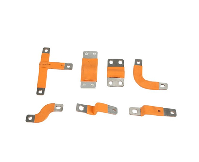
The copper foil Flexible Busbar is a critical component in modern new energy power battery systems, particularly in electric vehicles (EVs) and energy storage applications. This advanced conductive element combines the excellent electrical properties of copper with the mechanical flexibility required for dynamic battery pack configurations. With the rapid growth of the EV market (projected to reach $1.5 trillion by 2030), the demand for high-performance busbars has increased significantly.

1. High Conductivity: Copper foil busbars offer exceptional electrical conductivity of ≥58 MS/m (100% IACS), significantly reducing energy losses compared to aluminum alternatives. This results in improved system efficiency with typical power loss reductions of 15-20% in high-current applications.
2. Flexibility and Vibration Resistance: The laminated copper foil structure provides outstanding flexibility with bending radii as low as 5mm without performance degradation. This allows for ±2mm movement compensation between battery cells, crucial for automotive applications experiencing vibration frequencies up to 2000Hz.
3. Thermal Performance: With a thermal conductivity of 401 W/m·K, these busbars effectively dissipate heat, maintaining temperatures below 85°C even at current densities up to 30A/mm². The thermal expansion coefficient of 17 ppm/°C closely matches battery materials, reducing thermal stress.
4. Weight and Space Efficiency: The ultra-thin design (0.1-0.3mm thickness) provides a 40-50% weight reduction compared to traditional rigid busbars, while the compact form factor saves up to 30% space in battery pack designs.
5. Corrosion Resistance: Advanced surface treatments including tin plating (2-5μm) or nickel plating (3-8μm) provide excellent corrosion resistance, withstanding salt spray tests for 500+ hours (ASTM B117 standard).
Electric Vehicle Battery Packs: Used in modern EV battery systems (typically 400V-800V architectures) to connect lithium-ion cells with current carrying capacities up to 300A continuous. Particularly valuable in pouch cell configurations where flexibility is essential.
Energy Storage Systems (ESS): Deployed in grid-scale battery storage (1MWh+ systems) where thermal cycling between -40°C to +85°C requires durable, flexible interconnections between battery modules.
Hybrid Electric Vehicles: Ideal for HEV applications where space constraints demand compact, lightweight solutions with current densities up to 25A/mm².
Aerospace Battery Systems: Used in aircraft and satellite power systems where weight savings are critical (up to 60% lighter than conventional solutions) and vibration resistance is mandatory.
Portable Power Equipment: Applied in high-power mobile devices requiring flexible connections that can withstand 10,000+ bending cycles without failure.
Proper maintenance of copper foil Flexible Busbars is essential for ensuring long-term performance and reliability in new energy battery applications:
1. Regular Inspection: Conduct visual inspections every 6 months or 10,000 operating hours (whichever comes first) for signs of oxidation, discoloration, or mechanical damage. Use thermal imaging to check for hot spots exceeding 10°C above ambient temperature.
2. Cleaning Procedures: For surface contamination, use only approved non-abrasive cleaners with pH between 6-8. Isopropyl alcohol (≥99% purity) is recommended for removing oxidation. Avoid mechanical scrubbing that might damage the 2-8μm protective plating.
3. Torque Monitoring: For bolted connections, verify torque values every 12 months or after 5,000 thermal cycles. Maintain torque within ±10% of manufacturer specifications (typically 4-6 Nm for M6 connections).
4. Environmental Protection: In high-humidity environments (>80% RH), apply dielectric grease to exposed connections. For marine applications, consider additional protective coatings with minimum IP67 rating.
5. Bend Cycle Management: Document all maintenance-induced flexing and limit total bending cycles to <80% of rated maximum (typically 50,000 cycles for automotive-grade busbars). Avoid sharp bends beyond the specified 5mm radius.
Always handle with clean gloves to prevent contamination from skin oils
Use torque wrenches calibrated to ±2% accuracy for terminal connections
Maintain minimum clearance distances of 8mm between adjacent busbars
Allow for ±1mm movement accommodation in mounting designs
Perform resistance measurements after installation (target <50μΩ per connection)
Understanding common failure modes helps in preventive maintenance:
Creep Deformation: Occurs under continuous stress at temperatures above 70°C - monitor for permanent deformation exceeding 2% of original length
Stress Relaxation: Contact pressure may decrease by 15-20% after 1,000 hours at elevated temperatures - retorque as needed
Intergranular Corrosion: In aggressive environments, inspect for grain boundary attack at 200x magnification annually
Fatigue Cracking: Check for microcracks after 20,000 vibration cycles in mobile applications