2025-07-17 09:33:33
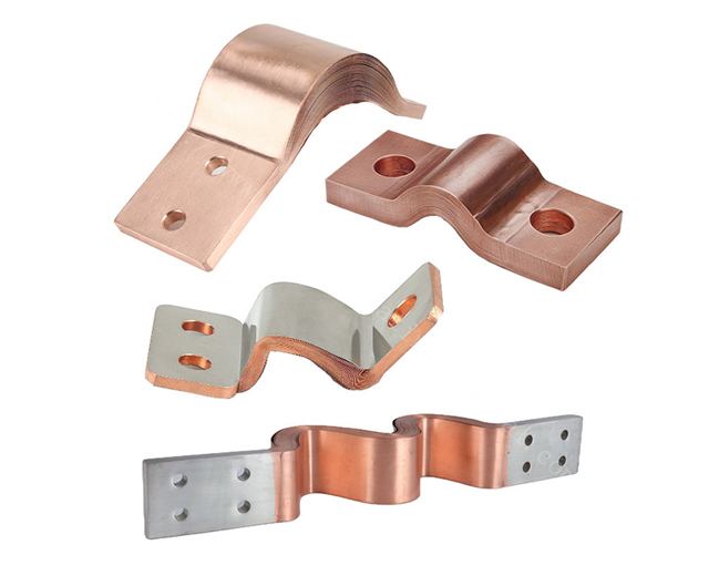
The Press Welded Copper Foil Flexible Busbar represents a significant advancement in electrical conduction technology, combining the superior conductivity of copper with innovative manufacturing techniques. This specialized component has become indispensable in modern power distribution systems where flexibility, reliability, and high current capacity are paramount requirements.

The Busbar is constructed from 99.9% pure electrolytic copper (C11000), ensuring optimal electrical conductivity with a typical value of 58 MS/m at 20°C. The copper foil thickness ranges from 0.1mm to 0.5mm, with standard widths between 10mm to 200mm.
The press welding process creates molecular bonds between copper layers without filler material, achieving a joint strength of ≥90% of base material strength. The welding temperature is precisely controlled at 500-600°C with pressures reaching 50-100 MPa.
The flexible design allows for ±30° angular movement and 5-10mm axial displacement while maintaining electrical continuity. The minimum bending radius is 5 times the busbar thickness for dynamic applications.
Current carrying capacity reaches 15-20 A/mm² in free air, with a temperature rise limited to ≤50K at rated current. The contact resistance is exceptionally low at ≤10 μΩ·cm.
Tensile strength measures 220-250 MPa, with elongation at break of 15-25%. The Vickers hardness ranges from 80-100 HV.
The thermal conductivity is 385 W/(m·K), with a maximum continuous operating temperature of 105°C and short-term withstand capability up to 250°C.
Standard options include tin plating (3-8μm), silver plating (2-5μm), or nickel plating (5-10μm), providing corrosion resistance with salt spray test performance exceeding 96 hours.
Used in battery pack interconnections, with typical specifications of 50mm × 0.3mm copper foil carrying 300-500A continuously. The flexibility accommodates 2-5mm thermal expansion in battery modules.
In solar inverters, 80mm × 0.4mm Busbars handle 600-800A while withstanding 15-25° panel movement in tracking systems.
For robotic arm power transmission, 30mm × 0.2mm versions support 10,000+ flex cycles at 1Hz operation frequency.
Busbars with 100mm × 0.5mm dimensions distribute 1000A+ to server racks with ≤1mV voltage drop per connection.
Lightweight 0.1mm foil versions weigh ≤50g/m while carrying 100A in constrained spaces.
Maintain bending radius ≥ 5× thickness during installation
Use torque-controlled fasteners at 5-10 N·m for terminal connections
Ensure parallel alignment within ±0.5mm for multi-layer configurations
Measure temperature rise quarterly, maintaining ≤65°C above ambient
Check contact resistance annually, with values ≤15 μΩ per joint
Inspect for mechanical fatigue every 10,000 cycles in dynamic applications
Use isopropyl alcohol (99.9%) for surface cleaning
Apply NO-OX-ID A-Special compound for plated surfaces every 2 years
Remove oxidation with 600-grit conductive abrasive when needed
Maintain environment at 15-30°C and 40-60% RH
Use vapor-corrosion inhibitor bags for periods > 3 months
Store flat with ≤50mm overhang to prevent deformation
Replace when cracks exceed 10% of width
Retire after 50,000 flex cycles or 20 years static service
Discard if resistance increases by >20% from initial values
The skin effect becomes significant at frequencies above 1kHz, with the 0.3mm foil thickness optimal for 50-400Hz applications. Proximity effect is minimized through ≥10mm spacing between parallel conductors.
Withstands 5-2000Hz random vibration at 5Grms for 2 hours per MIL-STD-810G. Natural frequency is typically 80-120Hz for 100mm spans.
Survives -40°C to +125°C thermal shock for 500 cycles with <2% resistance change. CTE matches PCB materials at 17 ppm/°C.